SUMMARY OF PIPE FAILURE ANALYSIS
Impact carried out pipe failure analysis testing and inspection on 10 sample elbow joints of pipes taken from a construction project, following a pipe failure on site.
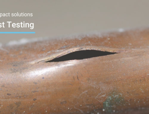
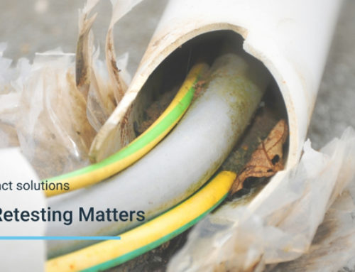
A visual inspection of the 10 joints raised a number of concerns in terms of the quality of installation that manifested itself as:
- Pipes not being fully inserted into the elbow
- Pipes misaligned
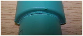
- The “weld bead” of polymer around the outside of the joint was inconsistent.
As agreed with the client, pressure testing was performed for a 2 hour period at 16 bar (1.5 x operating pressure) and 60°C (Normal operating temperature). After completing the prescribed test, the pressure was increased to 34 bar which 2 out of 3 samples also survived for over 24 hours. On completion of the pressure test, the joints were sectioned for examination, which confirmed the variability in the welding process.
Further samples were sectioned and the welds examined; despite a large number of them not having been installed according to the manufacturer’s specifications, they have formed a strong weld – the pipe could not be parted from the elbow by manual means.
An attempt was made to mechanically test the weld between the pipe and the elbow, but this was unsuccessful. A pull-out test would have been more informative, but could not be set up in the timescale available.
Two samples failed in a brittle manner when flexed manually and these constitute weak joints, which may have failed the pressure test. In particular, when one joint was examined after sectioning it was found to be very poor with the pipe and joint being separated by a moderate amount of force. The other section of the elbow joint was also sectioned and this also suffered from very poor fusion.
It is our strong belief that these poor joints were the result of poor installation practice, either person or machine related.
Despite such a limited set of samples, the presence of 2 or potentially 3 unsatisfactory welds indicates a failure rate in excess of 10% and we strongly recommended further samples should be analysed to quantify the risk and define what remedial action should be taken.
Background of Pipe Failure Analysis
Our client supplied 10 sample elbow joints of Pipe taken from one of their construction projects; this followed a product failure on site (and subsequently there have been further failures). The pipe system operates at 60 °C and at a pressure of 10.5 bar.
Impact carried out the following tests….
- Definition of weld strength using some form of cleavage test along the general principles of the water industry standard WIS 4-32-08, which gives requirements for both electrofusion & butt welded joints for use in the water industry.
- Pressure testing in accordance with the manual for pipe commissioning at 1.5 times system pressure and additional tests at higher pressures.
- Inspection of all joints to assess the quality and consistency of the welds.
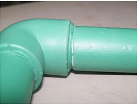
The elbow joints were thoroughly examined on receipt and each one was photographed. The condition of the joints was found to be variable; in some cases, misalignment of the pipe in the elbow joint was observed; in some cases, the pipe had not been fully inserted; in addition, the quality of the weld bead was found to vary considerably. These variations are illustrated in the following figures.
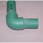
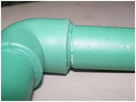
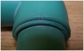
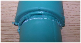
Figures 3 to 5 illustrate three levels of well bead formation – good (G), intermediate (S) and poor (B).
The samples supplied were assessed according to the above classification and the results are recorded below.
On the basis of this assessment and the size of the samples, some samples were allocated for pressure testing, some retained for mechanical testing (pull-out) and some were only suitable for sectioning and examination.
| Initial Visual Inspection of Pipe Failure Analysis | Test/Inspection |
| 2xS | P Testing |
| 1xG, 1xS | Retained |
| 1xG, 1xB | Retained |
| 1xB, 1xS | Sectioned |
| 1xB, 1xS | P Testing |
| 2xG | Sectioned |
| 1xB, 1xS | Sectioned |
| 2xG | P Testing |
| 2xS | Sectioned |
| 1xB, 1xS | Sectioned |
Testing and Inspection Performed
Pressure Testing
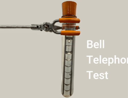
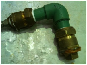
Samples were prepared using brass compression fittings as shown in Figure 6 and were conditioned at 60°C before pressurisation at 16 bar (1.5 operating pressure) for 10 minutes. Pressure was applied with water both internally and externally using calibrated test stations.
Figure 6: Pressure test configuration
Pressure was then increased to 34 bar in increments of 2 bar, holding each pressure increment for 30 minutes before increasing. Finally, the pressure was maintained at 34 bar for a duration of at least 24 hours.
Mechanical Testing
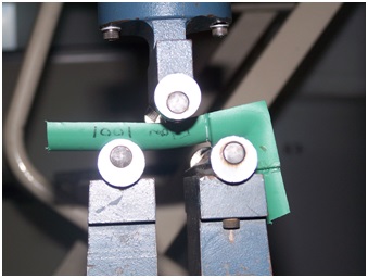
Following the sectioning of those selected samples, an attempt was made to measure the bond strength between the pipe and the elbow joint using a bending test on an Instron testing machine – see Figure 7 below. However, this was unsuccessful and two samples were retained intact for the set up of a pull-out test, which, it was hoped, would directly measure the bond strength between the pipe and the elbow.
Figure 7: Instron bend test set-up
Sectioning and Inspection of Pipe Failure Analysis
A number of samples were sectioned along the centre of the pipe and through the elbow. This was done in one direction than in the other to expose both of the joints at the elbow.
The cut half sections of pipe were then manually manipulated to see whether the bond between the pipe and the elbow could be broken.
The internal inspection of the welds was referenced against a benchmark sample supplied by the client, which had been prepared under controlled conditions. Figure 8 below shows the section cut through the weld and illustrates good insertion of the pipe – less than 2mm between the end of the pipe and the end stop in the elbow – and the presence of molten material at the end of the pipe.
Figure 8: Benchmark weld
Results of Pipe Failure Analysis
The following table records the results of testing or inspection as appropriate.
| Initial Visual Inspection | Test/Inspection | Results | Photos at Figure # |
| 2xS | P Testing | Passed initial 2h test at 16 bar, but failed after 2.5h at 34 bar. This sample was sectioned following the pressure test. | 9 |
| 1xG, 1xS | P Testing | Ongoing | |
| 1xG, 1xB | P Testing | Ongoing | |
| 1xB, 1xS | Sectioned | Some evidence of weld bead at both joints.Failed attempt to debond half pipe section from elbow using Instron 3 point bend test. | 10 |
| 1xB, 1xS | P Testing | Passed initial 2h test at 16 bar and ongoing at 34 bar after >73 hours | |
| 2xG | Sectioned | Likelihood of good adhesion of pipe to elbow at both joints. | 11 |
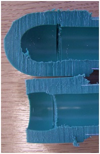
| 1xB, 1xS | Sectioned | Poor adhesion of pipe to elbow at both joints. | 12,13 |
| 2xG | P Testing | Passed initial 2h test at 16 bar and removed after 24h at 34 bar. This sample was sectioned following the pressure test. | 14 |
| 2xS | Sectioned | Poor adhesion of pipe to elbow on one of the joints. Weld bead at other joint. | 15 |
| 1xB, 1xS | Sectioned | Some evidence of weld bead at both joints.Attempt to remove half section of pipe from elbow resulted in pipe failure. | 16 |
Figure 9: Sections of sample
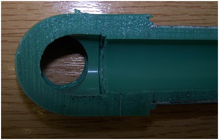
Figure 9 shows the section through the weld joint which failed after 2.5 hours at 34bar, but there was no obvious failure path shown. This joint shows a weld bead and good insertion.
Figure 10: Sections of sample
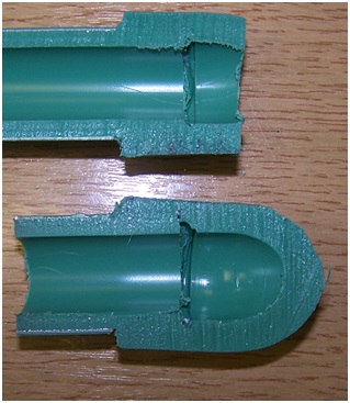
Figure 10 shows the section through the weld joint which was mechanically tested; again weld bead and reasonable insertion shown.
Figure 11: Sections of sample
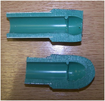
Figure 11 shows a section only – no testing – reasonable weld likely as weld bead is evident
Figure 12: Sections of sample
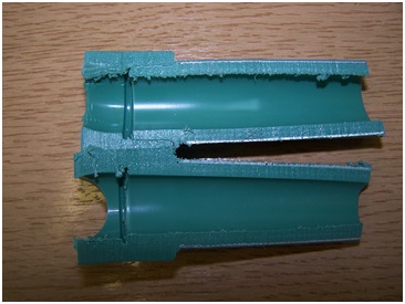
Figure 12 shows a section of the very poor joint – no weld bead in evidence. The weld surfaces for this joint are shown below in Figure 13 to illustrate very little melting and consequent low level of adhesion.
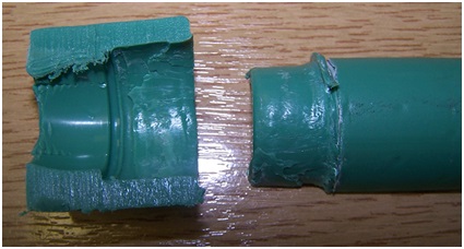
Figure 13: Section of sample showing very poor adhesion
Figure 14: Section of sample – following pressure test
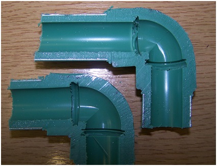
Figure 14 shows a section through, which had been tested at 16 bar for 2 hours and 34 bar for 24 hours – evidence of a weld bead, but poor insertion leaving a 5mm gap between the pipe end and the end stop in the elbow.
Figure 15: Section of sample
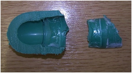
Figure 15 shows another poor weld for sample
Figure 16: Section of sample
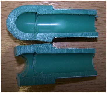
Figure 16 shows 1008R, which was a good weld and an attempt to part the pipe section from the elbow caused failure of the pipe.
Conclusions of Pipe Failure Analysis
This mainly qualitative assessment of selected samples from the construction project has shown that there is a great deal of variability in the quality of welds. There is significant variation in the extent of the weld bead and the extent to which the pipe has been inserted into the elbow.
In two cases out of the eight examined, poor adhesion has been detected between the pipe and the elbow.
It is most likely that this has occurred as a result of either (i) inconsistent implementation of the welding technique or (ii) inconsistency in the operation of the welding equipment.
Since >10% of the samples tested had inadequate fusion, if extrapolated to the entire building this would represent a large and (probably) unacceptable number of joint failures. In addition, because of the random nature of the weld quality, it could not be predicted when the failures might occur.
It was not possible to predict the quality of the weld from visual assessment of either the outside or the inside of the joint – the outcome of this is that a tighter quality control regime is required to ensure the integrity of such a system.
For more information please contact us info@impact-solutions.co.uk