Plastic Film Testing – Tear resistance and puncture resistance for film
Two of the key properties of flexible plastic film and sheeting which Impact Solutions regularly undertakes as part of film testing are the resistance to tear and/or puncture. The manufacture of thin flexible films and sheets, produced from polyolefins, commonly introduces orientation effects, which can lead to unbalanced properties in the machine and transverse directions. It is important to consider this when assessing the performance of thin films and sheets.
The Elmendorf test is a popular technique for determining tear resistance in film testing. Several similar methods are based on the Elmendorf test, e.g., ASTM D1424, ASTM D1922, and ISO 1974. However, in this article, we will focus on the method specified in EN-ISO 6383 part 2. The principle covers all of the above tests.
A common approach to puncture resistance in film testing is to use a free-falling dart, as specified in ASTM D1709 or EN-ISO 7765-1. The ISO method described here covers what is known as the ‘staircase’ method.
Determination of the tear resistance using the Elmendorf test – EN-ISO 6383 part 2
The Elmendorf test determines the force required to propagate a tear through a specified distance and from a specified slit, cut in a test specimen of the thin flexible plastic sheeting or film, under specified conditions of loading. Films or sheets can be tested as single or multiple-ply.
The tear resistance test specified by this method is applied to specimens cut from semi-finished and finished products. It is suitable for controlling production and manufactured products and for acceptance or rejection testing under specifications for semi-finished and finished products, provided that the data for a particular material are acceptably reproducible.
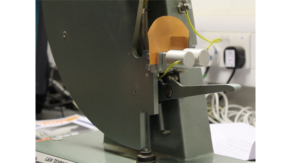
This film testing comprises a pendulum as shown in Figure 1 (a). The sample is held between two grips, which open and close by air-actuated valves, Figure 1 (b). One grip is attached to the pendulum whilst the other grip is held fixed on the base of the instrument. With the sample mounted in the grips, a 20mm notch is introduced into the bottom of the sample. The pendulum is then released causing the sample to tear into two pieces as shown in Figure 2(c). The force required to tear the film is recorded and shown on the instrument display.
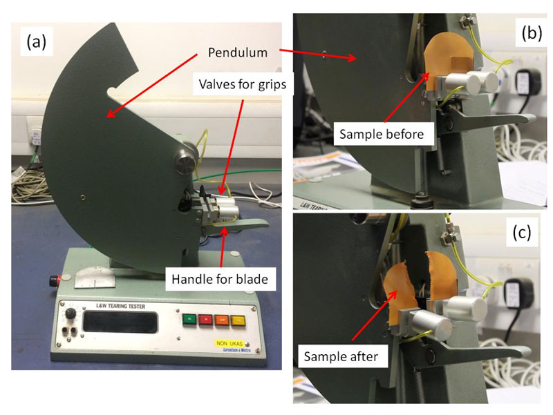
Figure 1 Elmendorf tear test
The preferred geometry is shown in the schematic of Figure 2. Samples are cut or stamped from the film usually in a direction parallel to the machine direction and perpendicular as shown in Figure 2.
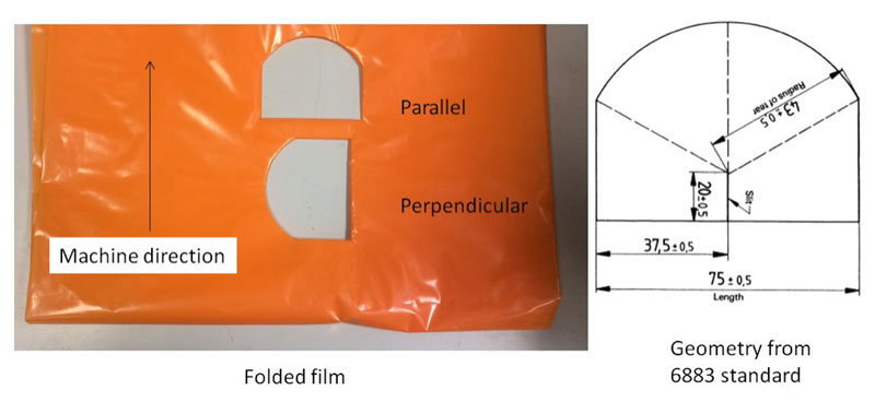
Figure 2 Preparation of samples for Elmendorf tear test
It is usual to undertake the test on at least 10 specimens and the average force in the parallel and perpendicular directions. It is often found that the tear resistance is lower in the parallel direction compared to the machine direction due to orientation effects from processing.
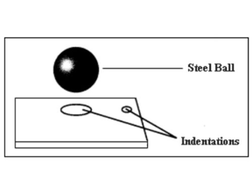
Determination of impact resistance – free falling dart method – BS EN 7765-1; 1988
The test arrangement is shown in Figure 3. The film is placed under the dart and a vacuum is used to pull the test area taught. A clamp is then placed over the film to hold it in place and prevent slippage. With appropriate weights, the dart is held and released from an electromagnet.
Impact Solutions uses equipment based on method A of the standard which requires a dart with a 38mm ± 1mm diameter hemispherical head dropped from a height of 0.66 ± 0.01m. The staircase method requires the missile weight to be decreased or increased by uniform increments (20g was used in the example shown) depending on the resulting failure or no failure observed for the specimen.
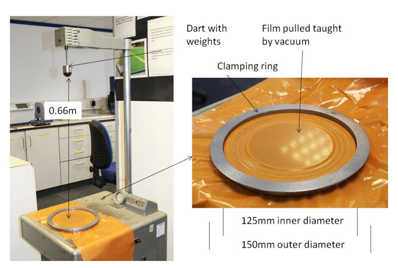
Figure 3 Preparation of samples for falling dart impact
Following the procedure of EN ISO 7765 a staircase graph showing the failure (red) and non-failure (green) results at different missile masses is shown in Figure 4. A total of 16 failures are shown; the 10th failure is circled. The failure mass using the staircase method is calculated as an example.
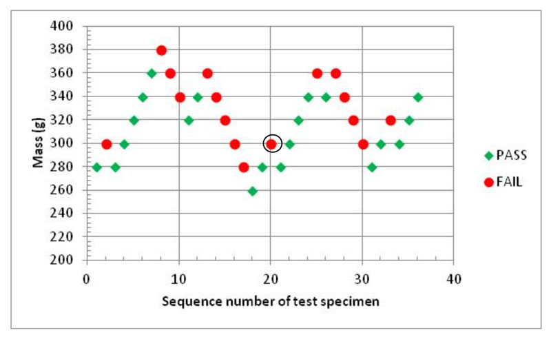
Figure 4 Staircase graph
To determine the impact failure mass in grams the following calculation is employed,
mf = mo + ∆m(A – 0.5)
N
mo = lowest failure mass = 280g
∆m = uniform mass increment = 20g
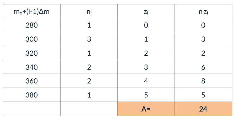
A= ∑nizi where ni is a number of test specimens failing at mass mi and zi is the number of mass increments from mo to mi (z=0 for mo). See the tables below which show how A is calculated.
N=sum of failed specimens =10 or 16
In the standard, the calculation is based on the set of data up to the 10th failure. Using A determined from Table 1. gives the failure mass as;
mf = 280 + 20 (24 – 0.5)
10
mf = 318g
Table 1 Calculation of A based on 10 failures
For more information and our full list of testing capabilities, click here, or contact a member of our team today!
Be sure to stay up-to-date with our testing capabilities by following us on Facebook, LinkedIn and Twitter.